Constant Voltage And Constant Current Controller . From a design and arc control standpoint, there are two fundamentally different types of welding power sources. The cc control loop also incorporates a current sense amplifier with gain of 10. Buy Constant voltage Constant current from www.aliexpress.com The voltage reference combined with one operational amplifier makes it an ideal voltage controller. The tsm1011 integrates one voltage reference and two operational amplifiers (with ored outputs —common collectors). The tsm1011 is a highly integrated solution for smps applications requiring cv (constant voltage) and cc (constant current) modes.
Variable Voltage Divider Circuit. If you need to divide the voltage, use a voltage divider. When the light shining on the ldr changes wavelength, the resistance of the circuit changes as shown in the graph.
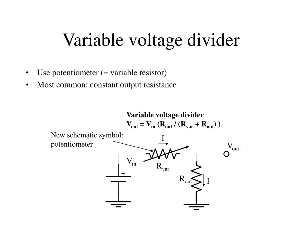
PPT Basic electronics PowerPoint Presentation, free from www.slideserve.com
When the light shining on the ldr changes wavelength, the resistance of the circuit changes as shown in the graph. V in = input voltage. Then, the voltage from the power supply is divided between both resistors.
Both Types Of Circuits Will Output A Variable Analog Voltage As The Sensor Resistance Changes As A Function Of Applied Force.
With respect to a common point or ground, usually 0v, or it could be across a dual supply, for example ±5v, or ±12v, etc. Let's get into the specific differences When the light shining on the ldr changes wavelength, the resistance of the circuit changes as shown in the graph.
If You Need To Divide The Voltage, Use A Voltage Divider.
Voltage division rule for above two resistor circuit. These voltage divider circuits also made provision for a small amount of “wasted” current through the divider called a bleeder current, designed to discharge the high voltage output of the power supply quickly. A voltage divider is a simple circuit which turns a large voltage into a smaller one.
This Circuit Is Very Useful For All Analog Circuits Where Variable Voltages Are Required, Hence It Is Important To Understand How This Circuit Works And How To Calculate The Values Of Resistors.
Using just two series resistors and an input voltage, we can create an output voltage that is a fraction of the input. It gives the output voltage (vo). R1 = resistor closest to input voltage (vin) r2 = resistor closest to ground.
The Third Circuit Is An Adjustable Voltage Regulator.
The required output voltage (vout) can be obtained across the resistor r2. A voltage divider circuit will normally look like this in a circuit with a series of 2 resistors. You can quickly design the circuit using the method presented here.
It Looks Like A Series Circuit.
Then, the voltage from the power supply is divided between both resistors. A potentiometer is a variable resistor connected as a potential divider to give a continuously variable output voltage. Therefore output voltage will be 11.43 v.


Comments
Post a Comment